A changing magnetic field creates an electric field; this phenomenon is described by the Maxwell-Faraday equation:[16]

where:
 denotes curl
- E is the electric field
- B is the magnetic field
This equation appears in modern sets of Maxwell's equations and is often referred to as Faraday's law. However, because it contains only partial time derivatives, its application is restricted to situations where the test charge is stationary in a time varying magnetic field. It does not account for electromagnetic induction in situations where a charged particle is moving in a magnetic field.
It also can be written in an integral form by the Kelvin-Stokes theorem:[17]


where the movement of the derivative before the integration requires a time-independent surface Σ (considered in this context to be part of the interpretation of the partial derivative), and as indicated in Figure 6:
- Σ is a surface bounded by the closed contour ∂Σ; both Σ and ∂Σ are fixed, independent of time
- E is the electric field,
- dℓ is an infinitesimal vector element of the contour ∂Σ,
- B is the magnetic field.
- dA is an infinitesimal vector element of surface Σ , whose magnitude is the area of an infinitesimal patch of surface, and whose direction is orthogonal to that surface patch.
Both dℓ and dA have a sign ambiguity; to get the correct sign, the right-hand rule is used, as explained in the article Kelvin-Stokes theorem. For a planar surface Σ, a positive path element dℓ of curve ∂Σ is defined by the right-hand rule as one that points with the fingers of the right hand when the thumb points in the direction of the normal n to the surface Σ.
The integral around ∂Σ is called a path integral or line integral. The surface integral at the right-hand side of the Maxwell-Faraday equation is the explicit expression for the magnetic flux ΦB through Σ. Notice that a nonzero path integral for E is different from the behavior of the electric field generated by charges. A charge-generated E-field can be expressed as the gradient of a scalar field that is a solution to Poisson's equation, and has a zero path integral. See gradient theorem.
The integral equation is true for any path ∂Σ through space, and any surface Σ for which that path is a boundary. Note, however, that ∂Σ and Σ are understood not to vary in time in this formula. This integral form cannot treat motional EMF because Σ is time-independent. Notice as well that this equation makes no reference to EMF  , and indeed cannot do so without introduction of the Lorentz force law to enable a calculation of work.

Using the complete Lorentz force to calculate the EMF,

a statement of Faraday's law of induction more general than the integral form of the Maxwell-Faraday equation is (see Lorentz force):


where ∂Σ(t) is the moving closed path bounding the moving surface Σ(t), and v is the velocity of movement. See Figure 2. Notice that the ordinary time derivative is used, not a partial time derivative, implying the time variation of Σ(t) must be included in the differentiation. In the integrand the element of the curve dℓ moves with velocity v.
Figure 7 provides an interpretation of the magnetic force contribution to the EMF on the left side of the above equation. The area swept out by segment dℓ of curve ∂Σ in time dt when moving with velocity v is (see geometric meaning of cross-product):

so the change in magnetic flux ΔΦB through the portion of the surface enclosed by ∂Σ in time dt is:

and if we add these ΔΦB-contributions around the loop for all segments dℓ, we obtain the magnetic force contribution to Faraday's law. That is, this term is related to motional EMF.
[edit] Example: viewpoint of a moving observer
Revisiting the example of Figure 3 in a moving frame of reference brings out the close connection between E- and B-fields, and between motional and induced EMF's.[18] Imagine an observer of the loop moving with the loop. The observer calculates the EMF around the loop using both the Lorentz force law and Faraday's law of induction. Because this observer moves with the loop, the observer sees no movement of the loop, and zero v × B. However, because the B-field varies with position x, the moving observer sees a time-varying magnetic field, namely:
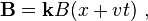
where k is a unit vector pointing in the z-direction.[19]
[edit] Lorentz force law version
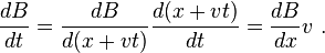
The Maxwell-Faraday equation says the moving observer sees an electric field Ey in the y-direction given by:


Here the chain rule is used:
Solving for Ey, to within a constant that contributes nothing to an integral around the loop,

Using the Lorentz force law, which has only an electric field component, the observer finds the EMF around the loop at a time t to be:
![\mathcal{E} = -\ell [ E_y (x_C+w/2,\ t) - E_y(x_C-w/2,\ t)]](http://upload.wikimedia.org/math/3/b/9/3b950e184ab5d52e2b6aae534a14559a.png)
![= v\ell [ B(x_C+w/2+v t) - B(x_C-w/2+vt)] \ ,](http://upload.wikimedia.org/math/3/c/a/3cacfe084d17fddf872aba14304b720e.png)
which is exactly the same result found by the stationary observer, who sees the centroid xC has advanced to a position xC + v t. However, the moving observer obtained the result under the impression that the Lorentz force had only an electric component, while the stationary observer thought the force had only a magnetic component.
[edit] Faraday's law of induction
Using Faraday's law of induction, the observer moving with xC sees a changing magnetic flux, but the loop does not appear to move: the center of the loop xC is fixed because the moving observer is moving with the loop. The flux is then:

where the minus sign comes from the normal to the surface pointing oppositely to the applied B-field. The EMF from Faraday's law of induction is now:


![=v\ell \ [ B(x_C+w/2+vt) - B(x_C-w/2+vt)] \ ,](http://upload.wikimedia.org/math/8/0/3/803906ede26061c543f9a171c6d242e7.png)
the same result. The time derivative passes through the integration because the limits of integration have no time dependence. Again, the chain rule was used to convert the time derivative to an x-derivative.
The stationary observer thought the EMF was a motional EMF, while the moving observer thought it was an induced EMF.[20]
[edit] Electrical generator

The EMF generated by Faraday's law of induction due to relative movement of a circuit and a magnetic field is the phenomenon underlying electrical generators. When a permanent magnet is moved relative to a conductor, or vice versa, an electromotive force is created. If the wire is connected through an electrical load, current will flow, and thus electrical energy is generated, converting the mechanical energy of motion to electrical energy. For example, the drum generator is based upon Figure 4. A different implementation of this idea is the Faraday's disc, shown in simplified form in Figure 8. Note that either the analysis of Figure 5, or direct application of the Lorentz force law, shows that a solid conducting disc works the same way.
In the Faraday's disc example, the disc is rotated in a uniform magnetic field perpendicular to the disc, causing a current to flow in the radial arm due to the Lorentz force. It is interesting to understand how it arises that mechanical work is necessary to drive this current. When the generated current flows through the conducting rim, a magnetic field is generated by this current through Ampere's circuital law (labeled "induced B" in Figure 8). The rim thus becomes an electromagnet that resists rotation of the disc (an example of Lenz's law). On the far side of the figure, the return current flows from the rotating arm through the far side of the rim to the bottom brush. The B-field induced by this return current opposes the applied B-field, tending to decrease the flux through that side of the circuit, opposing the increase in flux due to rotation. On the near side of the figure, the return current flows from the rotating arm through the near side of the rim to the bottom brush. The induced B-field increases the flux on this side of the circuit, opposing the decrease in flux due to rotation. Thus, both sides of the circuit generate an emf opposing the rotation. The energy required to keep the disc moving, despite this reactive force, is exactly equal to the electrical energy generated (plus energy wasted due to friction, Joule heating, and other inefficiencies). This behavior is common to all generators converting mechanical energy to electrical energy.
Although Faraday's law always describes the working of electrical generators, the detailed mechanism can differ in different cases. When the magnet is rotated around a stationary conductor, the changing magnetic field creates an electric field, as described by the Maxwell-Faraday equation, and that electric field pushes the charges through the wire. This case is called an induced EMF. On the other hand, when the magnet is stationary and the conductor is rotated, the moving charges experience a magnetic force (as described by the Lorentz force law), and this magnetic force pushes the charges through the wire. This case is called motional EMF. (For more information on motional EMF, induced EMF, Faraday's law, and the Lorentz force, see above example, and see Griffiths.)

0 comments:
Post a Comment