A related principle, Newton's law of cooling, states that the rate of heat loss of a body is proportional to the difference in temperatures between the body and its surroundings. The law is given as the differential equation:

- Q = Thermal energy in joules
- h = Heat transfer coefficient
- A = Surface area of the heat being transferred
- T = Temperature of the object's surface and interior (since these are the same in this approximation)
- Tenv = Temperature of the environment
- ΔT(t) = T(t) − Tenv is the time-dependent thermal gradient between environment and object
This form of heat loss principle is sometimes not very precise; an accurate formulation may require analysis of heat flow, based on the (transient) heat transfer equation in a nonhomogeneous, or else poorly conductive, medium. An analog for continuous gradients is Fourier's Law.
The following simplification (called lumped system thermal analysis and other similar terms) may be applied, so long as it is permitted by the Biot number, which relates surface conductance to interior thermal conductivity in a body. If this ratio permits, it shows that the body has relatively high internal conductivity, such that (to good approximation) the entire body is at the same uniform temperature throughout, even as this temperature changes as it is cooled from the outside, by the environment. If this is the case, these conditions give the behavior of exponential decay with time, of temperature of a body.
In such cases, the entire body is treated as lumped capacitance heat reservoir, with total heat content which is proportional to simple total heat capacity C , and T, the temperature of the body, or Q = C T. From the definition of heat capacity C comes the relation C = dQ/dT. Differentiating this equation with regard to time gives the identity (valid so long as temperatures in the object are uniform at any given time): dQ/dt = C (dT/dt). This expression may be used to replace dQ/dt in the first equation which begins this section, above. Then, if T(t) is the temperature of such a body at time t , and Tenv is the temperature of the environment around the body:

where
r = hA/C is a positive constant characteristic of the system, which must be in units of 1/time, and is therefore sometimes expressed in terms of a characteristic time constant t0 given by: r = 1/t0 = ΔT/[dT(t)/dt] . Thus, in thermal systems, t0 = C/hA. (The total heat capacity C of a system may be further represented by its mass-specific heat capacity cp multiplied by its mass m, so that the time constant t0 is also given by mcp/hA).
Thus the above equation may also be usefully written:

The solution of this differential equation, by standard methods of integration and substitution of boundary conditions, gives:

Here, T(t) is the temperature at time t, and T(0) is the initial temperature at zero time, or t = 0.
If:
 is defined as :
  where
where  is the initial temperature difference at time 0,
then the Newtonian solution is written as:

Uses: For example, simplified climate models may use Newtonian cooling instead of a full (and computationally expensive) radiation code to maintain atmospheric temperatures.
One dimensional application, using thermal circuits
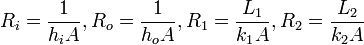
A very useful concept used in heat transfer applications is the representation of thermal transfer by what is known as thermal circuits. A thermal circuit is the representation of the resistance to heat flow as though it were an electrical resistor. The heat transferred is analogous to the current and the thermal resistance is analogous to the electric resistor. The value of the thermal resistance for the different modes of heat transfer are calculated as the denominators of the developed equations. The thermal resistances of the different modes of heat transfer are used in analyzing combined modes of heat transfer. The equations describing the three heat transfer modes and their thermal resistances, as discussed previously are summarized in the table below:
| Transfer Mode | Amount of Heat Transfer | Thermal Resistance |
|---|---|---|
| Conduction |  |  |
| Convection |  |  |
| Radiation | 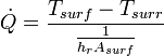 |   |
In cases where there is heat transfer through different media (for example through a composite), the equivalent resistance is the sum of the resistances of the components that make up the composite. Likely, in cases where there are different heat transfer modes, the total resistance is the sum of the resistances of the different modes. Using the thermal circuit concept, the amount of heat transferred through any medium is the quotient of the temperature change and the total thermal resistance of the medium. As an example, consider a composite wall of cross- sectional area A. The composite is made of an L1 long cement plaster with a thermal coefficient k1 and L2 long paper faced fiber glass, with thermal coefficient k2. The left surface of the wall is at Ti and exposed to air with a convective coefficient of hi. The Right surface of the wall is at To and exposed to air with convective coefficient ho.

Using the thermal resistance concept heat flow through the composite is as follows:

where
Insulation and radiant barriers
Thermal insulators are materials specifically designed to reduce the flow of heat by limiting conduction, convection, or both. Radiant barriers are materials which reflect radiation and therefore reduce the flow of heat from radiation sources. Good insulators are not necessarily good radiant barriers, and vice versa. Metal, for instance, is an excellent reflector and poor insulator.
The effectiveness of an insulator is indicated by its R- (resistance) value. The R-value of a material is the inverse of the conduction coefficient (k) multiplied by the thickness (d) of the insulator. The units of resistance value are in SI units: (K·m²/W)


Rigid fiberglass, a common insulation material, has an R-value of 4 per inch, while poured concrete, a poor insulator, has an R-value of 0.08 per inch.[7]
The effectiveness of a radiant barrier is indicated by its reflectivity, which is the fraction of radiation reflected. A material with a high reflectivity (at a given wavelength) has a low emissivity (at that same wavelength), and vice versa (at any specific wavelength, reflectivity = 1 - emissivity). An ideal radiant barrier would have a reflectivity of 1 and would therefore reflect 100% of incoming radiation. Vacuum bottles (Dewars) are 'silvered' to approach this. In space vacuum, satellites use multi-layer insulation which consists of many layers of aluminized (shiny) mylar to greatly reduce radiation heat transfer and control satellite temperature.
Critical insulation thickness
| | This section may require cleanup to meet Wikipedia's quality standards. Please improve this section if you can. (March 2009) |
| | This section may require copy editing for grammar, style, cohesion, tone or spelling. You can assist by editing it. (March 2009) |
Low thermal conductivity (k) materials reduce heat fluxes. The smaller the k value, the larger the corresponding thermal resistance (R) value.
The units of thermal conductivity(k) are W·m-1·K-1 (watts per meter per kelvin), therefore increasing width of insulation (x meters) decreases the k term and as discussed increases resistance.
This follows logic as increased resistance would be created with increased conduction path (x).
However, adding this layer of insulation also has the potential of increasing the surface area and hence thermal convection area (A).
An obvious example is a cylindrical pipe:
- As insulation gets thicker, outer radius increases and therefore surface area increases.
- The point where the added resistance of increasing insulation width becomes overshadowed by the effects of surface area is called the critical insulation thickness. In simple cylindrical pipes:[8]
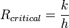
For a graph of this phenomenon in a cylidrical pipe example see: External Link: Critical Insulation Thickness diagram as at 26/03/09


0 comments:
Post a Comment